Jun 27, 2020
Spotlight
Edmonton Valley Line Light Rail Transit (ENG)
Client: City of Edmonton
Location: Edmonton, Alberta
Contract: Design-Build-Finance-Maintain
Size: 13 Km
Value: $1.8 billion
Project Highlights
- The largest infrastructure project in Edmonton’s history
- APEGA: Governmental Leadership in Sustainable Infrastructure
- 2021 Canada’s Top 100 Biggest Infrastructure Projects, ReNew Canada
- Elevated Guideways
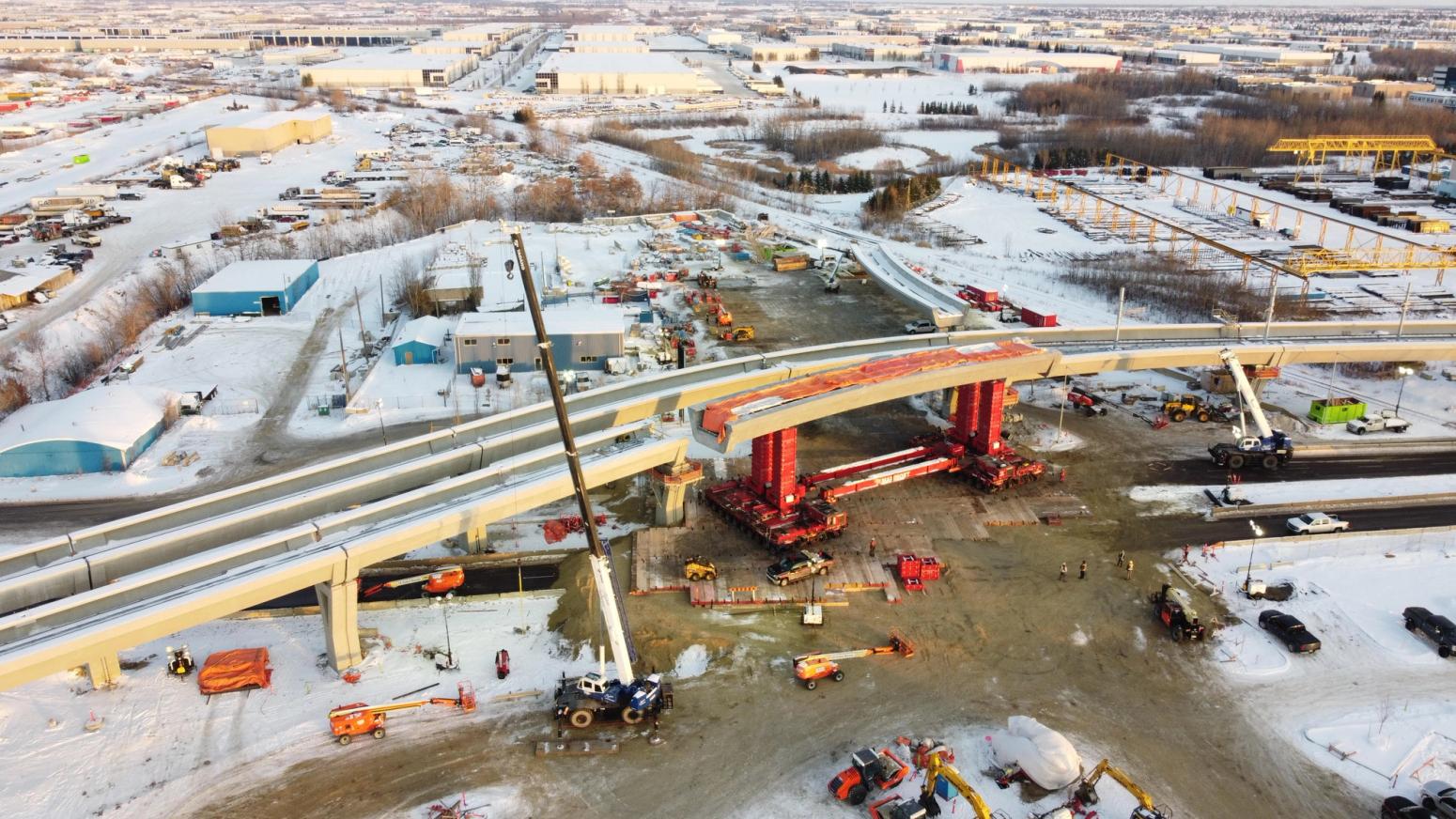
This project had over 44 elevated guideway spans for the trains that are installed over a wide variety of grade below (valleys, wildlife passes, roadways, and CN/CP train tracks). EllisDon’s Engineering team and Oxford Builders worked closely with the JV team to create an off-line production yard for casting the spans lower to the ground for improved safety, on casting beds that could be quickly reconfigured for a variety of span lengths, curves, and shapes. EllisDon’s engineering team was able to overcome the software challenges of the design team, creating the master 3D guideway geometry that integrated the pre-deflected shape and all geometric details and layout of the span curvature and slopes. This allowed the rebar fabricator to detail rebar into accurate models and for Mammoet (responsible for moving the spans from the casting beds to the final location) to provide a high level of accuracy and safety in key massing and stability calculations.
EllisDon’s Engineering team led the formwork design that leveraged a 5 formwork table support approach on the span. This allowed for the spans to be post-tensioned in the casting bed, shifting all weight to the end supports (tables 1 and 5), removing tables 2 and 4 for Mammoet to drive in the Self-Propelled-Modular-Transporters (SPMTs) under the span, and moving the span out of the bed. The Engineering team worked closely with ARUP (the Engineer of Record) to define the phased construction analysis of the span through the entire process.
Churchill Station (downtown integration)
The entrance for this station was extremely limited by the parcel of land provided by the city such that the total space required by the owner did not have sufficient land available to include traditional excavation shoring. EllisDon’s Ground Engineering worked with the station structural engineers to create a semi-top-down excavation approach that integrated the portions of the permanent structure as the excavation system. Concrete ring beams, later integrated into the foundation wall, were cast as work proceeded to brace the excavation until the rest of the station was constructed on the way back up.
Guideway Piers
The unique Y-shape of the guideway support piers required close integration of the concrete design, formwork design, and rebar design. The piers ranged in height from 6.0m to 12.7m. To create consistency in formwork design, the height variations were handled for a constant top shape/geometry with a consistent taper/slope to the height extension (top stayed consistent). EllisDon’s Building & Material Sciences team provided industry-leading support to the concrete design, working with the concrete supplier to create a self-consolidating concrete mix that avoids the need to vibrate the concrete (typically required by traditional concrete). The self-consolidating nature allows concrete to flow, providing extreme quality in the formwork finish and also navigating the dense rebar cage inside the pier. EllisDon’s Engineering team created a detailed 3D model of the entire rebar cage to identify early in the design constructability challenges on rebar detailing, reduce congestion, and facilitate permanent chutes inside the piers for the concrete pouring. EllisDon has more than 17 years of field-based (i.e. full scale) research into self-consolidating concrete, allowing a 30% reduction in formwork pressure on the pier design. EllisDon also introduced remote monitoring of curing and heating of the piers to monitor strength gain and potential temporary heater failures.